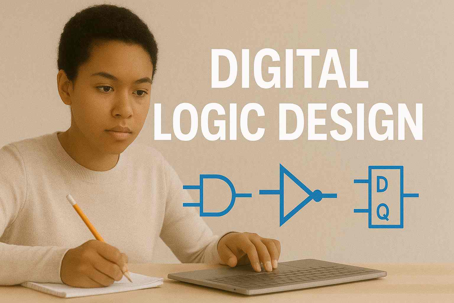
💡 What is Digital Logic Design?
Digital Logic Design is the foundation of how computers, calculators, and digital devices work. It involves:
✅ Using binary numbers (0 and 1)
✅ Creating logic circuits that make decisions
✅ Designing components like adders, multiplexers, and memory units
It’s like learning how a computer "thinks" using electricity and logic.
🔢 1. The Binary Number System
Computers use binary (base-2) because digital circuits have two voltage levels:
0 = LOW (off)
1 = HIGH (on)
Examples:
Decimal 5 → Binary 101
Decimal 12 → Binary 1100
You’ll also encounter:
Octal (base-8) and Hexadecimal (base-16) for short representations
Conversions between decimal ↔ binary ↔ hex
🧩 2. Logic Gates – Building Blocks of Digital Circuits
Logic gates are basic circuits that perform logical operations on binary inputs.
These are used to create circuits that add, compare, or control data.
📐 3. Boolean Algebra
Boolean algebra is the mathematics of logic.
✅ Variables take only two values: 0 and 1
✅ You can simplify logic expressions using Boolean laws:
Identity: A + 0 = A
Null: A · 0 = 0
Idempotent: A + A = A
Complement: A + A' = 1
Simplifying logic saves hardware and power.
🏗️ 4. Combinational Logic Circuits
Combinational circuits produce outputs based only on current inputs.
✅ Examples:
Half Adder and Full Adder (used in binary addition)
Multiplexer (MUX) – selects one input from many
Demultiplexer (DEMUX) – sends one input to multiple outputs
Encoder – converts input to binary code
Decoder – converts binary to output lines
These circuits are used in ALUs, CPUs, calculators, and embedded devices.
🔁 5. Sequential Logic Circuits
Sequential circuits depend on both inputs and previous states (memory).
Key components:
Flip-Flops – basic memory units (store 1 bit)
Registers – group of flip-flops (store multiple bits)
Counters – used in clocks, timers
Finite State Machines (FSM) – used in games, UI flows, automation
These circuits power everything from elevators to vending machines.
🔄 6. Difference: Combinational vs Sequential
🔋 7. Real-Life Applications of Digital Logic
✅ Microprocessors and CPUs
✅ Mobile phones and digital watches
✅ Traffic light controllers
✅ Remote controls and security systems
✅ ATM and banking hardware
✅ Robotic and automation systems
Every digital device you use is powered by digital logic design at its core.
🛠️ 8. Tools for Practicing Digital Logic
✅ Logisim – Free visual circuit simulator
✅ Proteus – Popular in universities for embedded circuit design
✅ Tinkercad Circuits – For visual logic simulation
✅ Paper & pen – Design logic tables, draw circuits, solve Boolean expressions
💼 Career Relevance
✅ Embedded System Engineer
✅ Digital Electronics Engineer
✅ Robotics Developer
✅ IoT Developer
✅ Firmware Developer
✅ Computer Hardware Technician
Digital logic is also essential for Computer Architecture and Assembly Language.
Comments (0)
Categories
Recent posts


Ethiopia University Exit Exam: What You ...
27 Jun 2023
Grade 12 Exam Preparation Ethiopia | ...
18 Mar 2025
How to Make Money Online in Ethiopia | ...
18 Mar 2025


